Currently, the inlet stage of multi-stage axial compressor is generally designed with highly loaded transonic stage, whose blade twist along height and meridional flow path change greatly. As the compressor aerodynamic load increases, not only the reverse pressure gradient in the flow direction increases, but also the circumferential pressure gradient increases, which will lead to more serious secondary flow. Therefore, it is necessary to develop a new aerodynamic design technology for high performance transonic compressors, one of which is to adopt specific hub contouring.
In recent years, with the improvement of three-dimensional design level, designers realize that the hub contouring with uniform axial shrinkage is not the optimal design. Different hub contourings will produce different design performance. LeJambre et al. used the concave hub contouring for a 11-stage high pressure axial compressor rotor. The results show that the radial force generated by the hub contouring can inhibit the root corner separation trend on blade suction surface. And the compressor pressure and efficiency are improved. On the basis of LeJambre’s research, Stringham et al. adopted the hub contouring technique in a 9-stage axial compressor. The results show that the thickest part of boundary layer moves upward from the corner of the hub suction surface near the middle chord, and the boundary layer in the corner is almost eliminated from the last 20% chord. Hoeger et al. conducted a comparative experiment on the flow characteristics of transonic cascades with linear and concave hub contourings, which reveal that concave hub contouring can unload the blade boundary layer near the hub to reduce the loss coefficient. In addition, the hub contouring not only affects the flow near the hub, but also affects the flow from the hub along the span to a considerable distance. Huang et al. adopted the asymmetric endwall contouring method to optimize a high-load compressor cascade. Compared with the planar cascade, it can change the secondary flow structure of the endwall. In addition, the asymmetric endwall generates a corner vortex near the suction surface, which inhibits the development of passage vortex to the suction surface and reduces the flow separation near the suction surface. Xu et al. studied the effects of four different hub contourings on the performance of transonic rotor at the inlet of a compressor. The results show that the hub contouring mainly changes the performance by changing the load distribution on blade surface, reducing or increasing the root blockage and changing the strength of the radial flow. Yang et al. optimized the hub contouring of a transonic inlet fan by using the traditional area rule method of external flow. The results show that the flow field near rotor blade tip is improved, which results in a decrease in the overall loss. Cui et al. proposed the blockage area rule of hub contouring for multistage axial compressor. On this basis, the hub contouring of a four-stage axial compressor was optimized. The results show that the hub contouring modification can reduce the compressor blockage and make the stages matching more reasonable. Li et al. optimized hub contouring of the inlet transonic rotor of a four-stage compressor. The results show that the optimized contouring can improve the shock structure and compressor performance. Sun et al. studied three shapes of hub contouring in a transonic rotor with high load and low reaction. The results show that the slope of the endwall affects the location and intensity of corner separation. In addition, the hub contouring will also change the axial velocity and static pressure distribution along the flow direction, thereby affecting the maximum load position on blade.
The above researches about hub contouring focus on subsonic and transonic compressor rotor, high-load compressor cascade. Generally, it will have a significant impact on the flow field of the next row of rotor blade when the hub contouring changes. In addition, compressor designers prefer to use low hub-tip ratio design to obtain greater flow capacity recently. Consequently, the relative thickness of endwall boundary layer will also be reduced at the same time. The effect of hub contouring on a low hub-tip ratio compressor needs to be studied further. Therefore, in order to study the above problems, this paper takes a 1.5-stage transonic compressor with low hub-tip ratio and aspect ratio as the research object. Firstly, the influence of hub contouring on rotor performance is studied. Secondly, the influence of hub contouring on stator flow field is considered to explore its influence on compressor stage performance.
Research Object and Hub Contourings
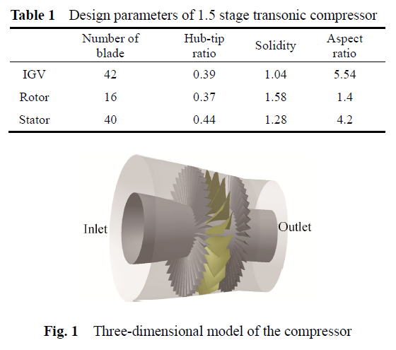
The research object of this paper is the inlet transonic 1.5 stage of a high pressure multi-stage axial compressor, which consists of three rows of blades, the inlet guide vane, the rotor blade and the stator vane. The basic design parameters of the compressor are shown in Table 1. The three-dimensional model of the compressor is shown in Fig. 1.
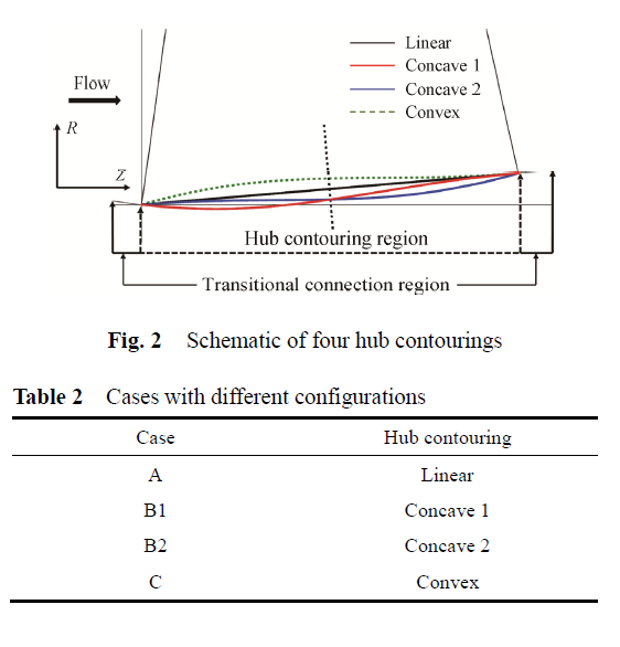
In order to study the influence of hub contouring on the flow field and performance of the transonic compressor, four hub contourings are designed in this paper: linear, convex and two concave types, as shown in Fig. 2. The original hub contouring of rotor blade is linear, named Linear. Concave 1 and Concave 2 are both Concave curves, which are symmetric curves about the black dotted line. The green dotted curve is convex, which is the symmetric curve of Concave 1. In order to ensure the smoothness and continuity of the four curves, all of them are constructed by two segments of 3 order Bezier curves. The hub curves at leading edge and trailing edge of rotor blade are connected by transition curves with the rest of hub curve to ensure that the curvature of the entire hub curve is continuous. The cases with different configurations are listed in Table 2.
Numerical Method
In this paper, the NUMECA Fine/Turbo solver is used for steady three-dimensional numerical simulation. The finite volume scheme and the Spalart-Allmaras turbulence model are used to solve the three-dimensional compressible Reynolds averaged Navier-Stokes equations of each component in the relative coordinate system, and the working fluid is perfect air. The steady-state flow solution is achieved at the convergence of a four stage explicit Runge-Kutta integration scheme, and the multi-grid method is used to accelerate the convergence. The inlet is the standard atmospheric condition, and the total temperature, total pressure and flow angle are given. Mass flow rate is given as outlet boundary at design condition and static pressure is given at other conditions. The solid wall is adiabatic and non-slip condition. For the four types of hub contouring, the same grid topology is adopted. The calculation conditions are consistent, so as to eliminate the influence of factors such as grid and boundary set on the calculation results.
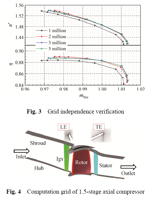
To assess the influence of computational grid size on the accuracy of calculation results, the study of grid independence was carried out on four different amount of grids. It is found in Fig. 3 that the simulation results tend to be consistent when the grid size exceeds 3 million. The computational grids of the four hub contourings are all about 3.2 million, and the grid of the rotor domain is about 1.4 million. The rotor tip clearance is 0.4 mm, and 17 layers of grids are arranged radially in the clearance to capture the change of clearance flow as accurately as possible. The grid diagrammatic sketch is shown in Fig. 4.
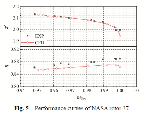
The transonic compressor of NASA rotor 37 is used as the research object to verify the numerical calculation method. The comparison between the calculated performance curve and experimental data is shown in Fig. 5. The total pressure ratio is in good agreement with the experimental results, where the calculated peak efficiency is about 2% lower than the experimental value. The above results are mainly consistent with the calculation results given in Refs., which indicates that the calculation method used in this paper is reliable.
Conclusions
Rotor hub contouring plays an essential role in compressor designing process. The effects of four hub contourings on performance of a 1.5-stage transonic axial compressor have been studied. Further, detailed flow field analysis of different cases at rotor peak efficiency condition is performed. Some conclusions are summarized as follows:
(1) For stage performance, the concave hub contouring, as Case B1 and B2, are conducive to improving the compressor flow capacity and work capacity. The stage pressure ratio curve of Cases B1 and B2 moves up right compared to Case A. The convex hub contouring, as Case C, has the opposite effect on the work capacity and flow capacity of the compressor compared to the concave hub contouring. The peak stage efficiency of four cases changes little. Case C has considerable stall margin enhancement while the other three cases have almost the same stall margin. For rotor performance, the change trend of rotor pressure ratio curve is almost the same as the stage pressure ratio curve. Case B2 has the highest rotor peak efficiency and the case C has the lowest rotor peak efficiency.
(2) The rotor corner separation and suction surface separation at 30% blade span can be inhabited by appropriate hub contouring. The change of flow field near hub region is attributed to the change of flow area caused by hub contouring, which affects the velocity distribution of airflow in blade passage.
(3) The hub contouring will change the load of rotor root, and this change will affect the load at the mid-span. The load change of the root is opposite to that of the mid-span, so is the load change of the rotor and stator. When the rotor root load changes, due to the effect of stage matching, the stator root load will make the opposite change. Therefore, the influence of hub contouring on stator performance should be considered comprehensively, especially when the load of stator root is large.
 Download the attachment
News