According to the Vision Flightpath 2050, aviation plays an important role in reducing noise and carbon dioxide emissions. To ensure competitive advantage in energy as well as environmental performance, the Collaborative Research Centre SFB 880 has conducted a research on active high-lift systems for future commercial transport. Mixed-flow compressor is an appropriate apparatus to realize the desired lift. It is embedded into the wing and can extract the boundary layer on the suction side of the airfoil. The boundary layer fluid then is ejected at the flap using the Coanda effect. Furthermore, to integrate the active system into the aircraft, one should focus on aerodynamic efficiency of the mixed-flow compressors to reduce power requirements. Therefore, the stage loading of the compressor is increased accompanied with enhanced unsteadiness, which induces serious instability problems including rotating stall.
There are two main kinds of rotating stall inception, namely spike-type and Modal-wave stall inception. Spike-type inception is more detrimental than modal-wave inception because it occurs only one or two revolutions before the stall. Stability enhancement methods are indispensable for widening the stall margin and to ensure the safety of passengers as well as the aviation system. Casing treatment (CT), one bright technology to extend the stall margin for spike-type compressors, has been used in modern aircraft engines. To increase the stability of the above-mentioned mixed-flow compressor, Du has designed an axial slot casing treatment (ASCT) and experimentally studied its effects on compressor performance. The results showed that the mixed-flow compressor with or without CT stalled via the spike stall inception, whereas the latest researches on axial-flow compressors showed that CT could alter the stall inception from spike-type to modal wave. Therefore, full-annulus simulations should be employed to demonstrate some phenomenon that is difficult to be observed in experiments.
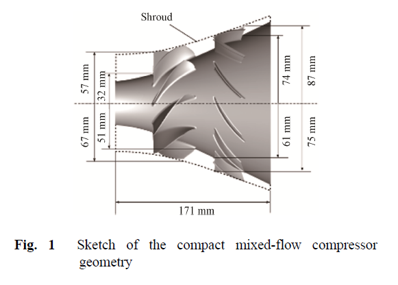
The test compressor is a compact highly-loaded mixed-flow compressor, and the relevant experiments were conducted at Leibniz University Hannover. This micro compressor is designed for an electrically powered active high-lift system in future civil aircrafts. The corrected rotational speed of the compressor is 60 125 r/min, and the corrected mass-flow rate is 1.11 kg/s at the design condition. For the predicted performance, this mixed-flow compressor has a polytropic efficiency of 83.3% and a total-to-total pressure ratio of 2.33. Fig. 1 shows the geometry of the mixed-flow compressor and Table 1 presents the key geometry parameters of the stage.
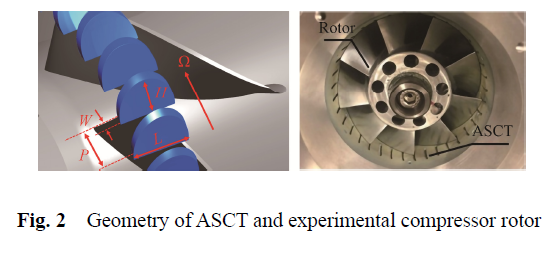
On the basis of the performance map of the compressor, the stall margin is less than 5% at the rotational speed of 40 000 r/min. To deal with this issue, Du designed a semi-circular ASCT as shown in Fig. 2 and experimentally validated its benefit to increase the stability at the part-speed for this mixed-flow compressor. Each blade passage is composed of four axial slots, and the applied CT is skewed with an angle of 60o inclined in the direction of rotor rotation. The length (L) and height (H) of the slots is 50%Cax (axial tip chord) and 30%Cax, respectively. The opening area ratio (W/P) of all the slots is 20%.
Measurement technique
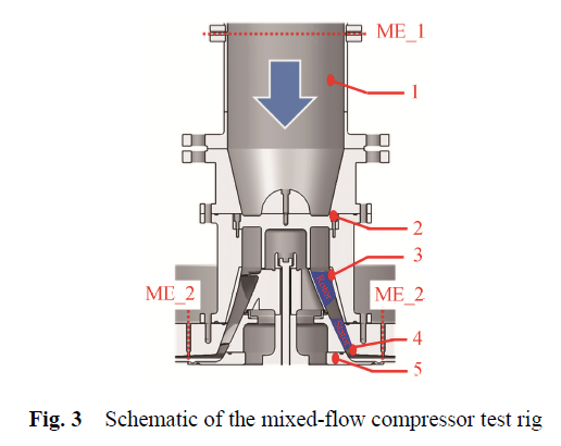
Fig. 3 shows a cross section of the test rig, where components 1–5 represent: inlet duct, branch transition, rotor, stator and outlet duct respectively. The flow enters into the rotor in the axial direction and it is turned by 90° to the radial direction downstream of the stator. In addition, ME1 and ME2 are the static pressure holes drilled at the inlet and the outlet sections.
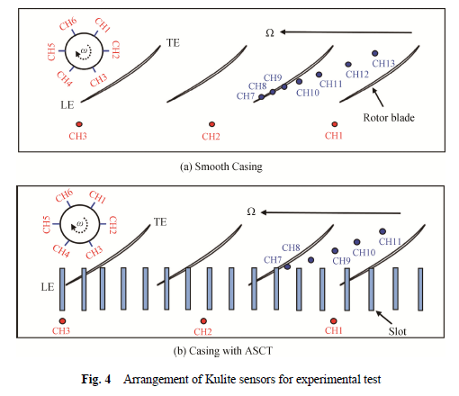
For the compressor with and without ASCT, the layout scheme of high-frequency “Kulite” pressure transducers is shown in Fig. 4(a) and Fig. 4(b). Six pressure transduces (CH1-CH6) were located circumferentially around the rotor blade upstream of rotor leading edge (LE), as demonstrated by the top-left corner diagram in Fig. 4(a). Moreover, seven pressure transducers (CH7-CH13) were positioned chordwise downstream of the rotor tip LE. Due to the presence of the ASCT, the sensor array in the axial direction was positioned downstream of the slots as shown in Fig. 4(b). The sampling rate of the unsteady measurement is 100 kHz. More details of the test facility and uncertainty analysis can be found.
Computational setup
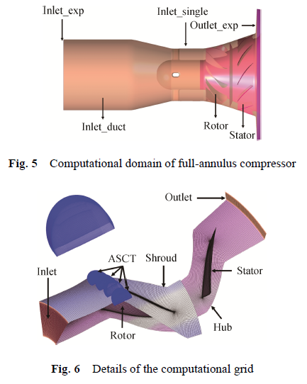
To investigate the effects of ASCT on the stall characteristics, a suite of simulations with and without ASCT were conducted at a rotational speed lower than the previous value, i.e., 30 000 r/min. The commercial solver, Ansys/CFX is employed to solve the Unsteady Reynolds-average Navier-Stokes equations with a full-annulus computational domain, which is consistent with the real geometry of the test rig, see Figure 5. The k-w turbulence model with second order discretization is adopted since it can well predict the operating range similar to the experimental result.
Fig. 6 shows details of the computational gird, where only one single-passage is presented for the sake of clarity. There are 16.2 million girds in total. Meanwhile, grid of the casing treatment region is also displayed; it contains 0.34 million nodes, which is enough to accurately capture the flow field pattern in blade tip in each single passage. A total of 17 nodes were distributed in the radial tip clearance, and the first grid spacing is set to 3×10⁻⁶ m to ensure that y+ is lower than 2. Smooth non-slip and adiabatic conditions are defined on all solid walls. The total pressure, the total temperature, and the velocity direction are given at the inlet, while a throttle valve model is adopted at the outlet to model off-design conditions. This throttle valve model is proved to be appropriate to simulate the stall transient process as the pressure is a function of the mass flow rate.
Unsteady simulations were conducted adopting 40 time-step per rotor blade period with a physical time step of 5.55×10⁻⁶ s, and 4 inner iterations were set each time to save computing resources. Sliding mesh interface (Transient Rotor Stator) is adopted between rotor passage and stator passage to exchange flow data. Since the slots were linked to the moving rotor passage, the slot-rotor interface was also modeled using unsteady rotor-stator interface. The unsteady simulation convergence is judged by observing the periodic fluctuation of all monitoring parameters in the flow field.
Numerical accuracy validation
The numerical results are validated using the experimental data. Fig. 7 shows the calculated (Cal) and measured (Exp) performance map of the compressor with and without ASCT. It is worth mentioning that the outlet total pressure is not measured in the tests, since the total pressure probes can disturb the flow field at the outlet where the distance between hub and shroud is less than 10 mm. Therefore, the overall performance map is generated in terms of static-to-static pressure ratio, where the static pressure is measured close to the casing wall. It can be seen from Fig. 7 that the discrepancy between the experimental data and the numerical results is fairly small, and the predictive error considering the stall limit is no more than 1%. This indicates that the current numerical model is adequate to clarify the key flow mechanisms, and hence it can be further employed to study the effect of ASCT.

Conclusions
The stall characteristics of a mixed-flow compressor with and without casing treatment (CT) are studied in this paper via experimental test. Full annulus, unsteady simulations are also conducted to clarify details of the unsteady flow field during the stall process. To reveal the flow structure that induces spike-type stall inception, three-dimensional flow field in several passages of the compressor with and without CT is analyzed in detail. The main conclusions are summarized as blow:
(1) The experimental results show that for smooth casing case, the interface between tip leakage flow and main flow is gradually moved forward to the rotor leading edge during the throttling process. The spike-type stall inception is appeared when the interface is parallel to the rotor leading edge. Almost identical circumferential propagating speed of spike inception is also resolved when analysing the unsteady simulation results. This proves the effectiveness of the throttle valve model in simulating the stall process.
(2) A spiky wave is identified based on the non-dimensional instantaneous static pressure traces at 32.6% of axial chord upstream of the leading edge, and it is represented by a low-pressure region adjacent to a high-pressure region. The low-pressure region corresponds to the shed vortex, and the high-pressure region is caused by the blocked passages. Both leading edge spillage and tip leakage backflow from trailing edge can be observed. The characteristics of rotating stall for this high-load mixed-flow compressor with and without ASCT are similar to that in axial-flow compressors. Hence, the addition of ASCT cannot change the stall characteristics for the mixed-flow compressor. This result offers a useful reference for the design and stall warning for the highly-load adaptive compressors of next-generation aeroengines and high-lift aviation system.
(3) In the throttling process, the leading-edge separation is gradually deteriorated because of the increase in incidence angle. Then this leading-edge separation vortex and the tip-leakage vortex are merged to form a tornado vortex. Due to the blockage effect of the tornado vortex and the increasing meridional radius of the mixed-flow compressor, the flow below the midspan is rolled up to enhance the passage vortex, which will disturb the tornado vortex in turn if the mass flow rate is further reduced, and leads to the blockage of the entire flow passage. Therefore, the high-pressure region responsible for the upward spike is induced by the blockage of this strong passage vortex. Meanwhile, the tip leakage flow is inhibited and cannot form into leakage vortex under the reduced tip blade loading. It is spilled into the next passage, and increases the incidence of the adjacent blade. Consequently, a new leading separation vortex is formed on the suction surface of the adjacent blade, and it will be further developed into a tornado vortex. In general, the low-pressure region relevant to the downward spike is caused by these leading-edge separation or tornado vortices.
 Download the attachment
News